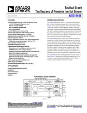
●The ADIS16488A series iSensor® Inertial Sensor System that includes a 3-axis gyroscope, a 3-axis accelerometer, 3-axis magnetometer and pressure sensor. Each inertial sensor in the ADIS16488A combines industry-leading iMEMS® technology with signal conditioning that optimizes dynamic performance. The factory calibration characterizes each sensor for sensitivity, bias, alignment and linear acceleration (gyroscope bias). As a result, each sensor has its own dynamic compensation formulas that provide accurate sensor measurements. The ADIS16488A provides a simple method for integrating accurate, multi-axis inertial sensing into industrial systems, especially when compared with the complexity and investment associated with discrete designs. All necessary motion testing and calibration are part of the production process at the factory, greatly reducing system integration time. Tight orthogonal alignment simplifies inertial frame alignment in navigation systems.
● SPI and register structure provide a simple interface for data collection and configuration control
● ±0.05° Orthogonal alignment error
● 5.1°/hr. In-run bias stability
● 0.26°/√hr. Angular random walk
● 0.01% Nonlinearity
● Triaxial, delta angle and delta velocity outputs
● Triaxial, digital magnetometer, ±2.5 gauss
● Digital pressure sensor, 300mbar to 1100mbar
● Fast start-up time
● Factory-calibrated sensitivity, bias and axial alignment
● Automatic and manual bias correction controls
● 4 FIR filter banks, 120 configurable taps
● Digital input/output - Data-ready alarm indicator, external clock
● Alarms for condition monitoring
● Power-down/sleep mode for power management
● Optional external sample clock input up to 2.4kHz
● Single command self test
● 2000g Shock survivability