Web Analytics
Part Datasheet Search > Analog Switches > MAX4712 Datasheet PDF
Images are for reference

MAX4712 Datasheet PDF

Part Series:
MAX4712 Series
Category:
Analog Switches
Description:
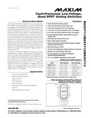
MAXIM INTEGRATED PRODUCTS MAX4712EUE+ Analog Switch, Fault Protected, SPST - NO, 4Channels, 25Ω, 2.7V to 11V, ± 2.7V to ± 5.5V, TSSOP
Updated Time: 2023/01/13 03:31:21 (UTC + 8)

MAX4712 Analog Switches Datasheet PDF

MAX4712 Datasheet PDF Analog Switches

18 Pages
Maxim Integrated
Analog Switch Quad SPST 16Pin SOIC N
18 Pages
Maxim Integrated
Analog Switch Quad SPST 16Pin SOIC N T/R
17 Pages
Maxim Integrated
Analog Switch Quad SPST 16Pin SOIC N T/R
17 Pages
Maxim Integrated
Analog Switch Quad SPST 16Pin TSSOP T/R
17 Pages
Maxim Integrated
Analog Switch Quad SPST 16Pin TSSOP
17 Pages
Maxim Integrated
Analog Switch Quad SPST 16Pin TSSOP T/R
17 Pages
Maxim Integrated
Analog Switch Quad SPST 16Pin SOIC N
17 Pages
Maxim Integrated
IC SWITCH QUAD SPST 16SOIC
17 Pages
Maxim Integrated
Analog Switch Quad SPST 16Pin PDIP N
17 Pages
Maxim Integrated
Analog Switch Quad SPST 16Pin SOIC N T/R
17 Pages
Maxim Integrated
Analog Switch ICs Fault-Protected, Low-Voltage, Quad SPST Analog Switch
17 Pages
Maxim Integrated
IC SW QUAD ANLG SPST R/R 16-DIP
17 Pages
Maxim Integrated
Analog Switch Quad SPST 16Pin TSSOP T/R

MAX4712EUE+ Specifications

TYPE
DESCRIPTION
Mounting Style
Surface Mount
Number of Pins
16 Pin
Case/Package
TSSOP-16
Number of Circuits
4 Circuit
Number of Channels
4 Channel
show more

MAX4712EUE+ Function Overview

The MAX4712EUE+ is a fault protected, low voltage, quad SPST analogue switch in 16 pin TSSOP package. It is constructed with two parallel FET"s allowing very low on-resistance. Due to the fault protection feature the analogue switch input (NO_ or NC_) and output (COM_) pins are not symmetrical. The fault protection feature allows for analogue input to go beyond the plus or minus supplies without the device drawing excessive amounts of current from the analogue inputs. When the analogue inputs are driven beyond the supply rails when the switch is on, it will sense a fault and turn itself off and the analogue switch output will be clamped to the same polarity supply as the input signal and will not go beyond the supply rails. This feature protects any electronic circuitry connected to the output from excessive voltages present on the analogue inputs. All digital inputs have +0.8V to +2.4V logic thresholds ensuring both TTL and CMOS logic compatibility.
Supply voltage range is 2.7V to 11V, ±2.7V to ±5.5V
Operating temperature range from -40°C to 85°C
Four normally closed switches
±12V fault protection with power off and ±7V fault protection with ±5V supplies
12V and -7V fault protection with +5V supply
12V and -9V fault protection with +3V supply
All switches off with power off
Rail to rail signal handling
Maximum on-resistance is 25ohm at dual supplies
Maximum on-resistance match between channels is 1ohm at dual supplies
show more
Part Datasheet PDF Search
Loading...
72,405,303 Parts Datasheet PDF, Update more than 5,000 PDF files ervery day.

Relate Parts