Part Datasheet Search > LED Drivers > PCA9685 User Reference Manual Guide
Images are for reference
PCA9685 User Reference Manual Guide
Part Series:
PCA9685 Series
Category:
LED Drivers
Description:
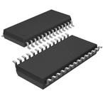
Led Driver, 16Outputs, PWM Dimming, 2.3V-5.5V in, 1MHz switch, 5.5V/25mA out, TSSOP-24
Updated Time: 2023/01/13 01:19:12 (UTC + 8)
PCA9685 LED Drivers User Reference Manual Guide
PCA9685 User Reference Manual Guide LED Drivers
64 Pages
NXP
Led Driver, 16Outputs, 2.3V-5.5V in, 1MHz switch, 5.5V/25mA out, TSSOP-28
PCA9685PW,112 - NXP Specifications
TYPE
DESCRIPTION
Mounting Style
Surface Mount
Frequency
25MHz, 50MHz
Number of Pins
28 Pin
Case/Package
TSSOP-28
Number of Outputs
16 Output
show more
PCA9685PW,112 - NXP Function Overview
●Overview
●The PCA9685 is an I²C-bus controlled 16-channel LED controller optimized for Red/Green/Blue/Amber (RGBA) color backlighting applications. Each LED output has its own 12-bit resolution (4096 steps) fixed frequency individual PWM controller that operates at a programmable frequency from a typical of 24 Hz to 1526 Hz with a duty cycle that is adjustable from 0 % to 100 % to allow the LED to be set to a specific brightness value. All outputs are set to the same PWM frequency.
●Each LED output can be off or on (no PWM control), or set at its individual PWM controller value. The LED output driver is programmed to be either open-drain with a 25 mA current sink capability at 5 V or totem pole with a 25 mA sink, 10 mA source capability at 5 V. The PCA9685 operates with a supply voltage range of 2.3 V to 5.5 V and the inputs and outputs are 5.5 V tolerant. LEDs can be directly connected to the LED output (up to 25 mA, 5.5 V) or controlled with external drivers and a minimum amount of discrete components for larger current or higher voltage LEDs.
●The PCA9685 is in the new Fast-mode Plus (Fm+) family. Fm+ devices offer higher frequency (up to 1 MHz) and more densely populated bus operation (up to 4000 pF).
●Although the PCA9635 and PCA9685 have many similar features, the PCA9685 has some unique features that make it more suitable for applications such as LCD or LED backlighting and Ambilight:
● The PCA9685 allows staggered LED output on and off times to minimize current surges. The on and off time delay is independently programmable for each of the 16 channels. This feature is not available in PCA9635.
● The PCA9685 has 4096 steps (12-bit PWM) of individual LED brightness control. The PCA9635 has only 256 steps (8-bit PWM).
● When multiple LED controllers are incorporated in a system, the PWM pulse widths between multiple devices may differ if PCA9635s are used. The PCA9685 has a programmable prescaler to adjust the PWM pulse widths of multiple devices.
● The PCA9685 has an external clock input pin that will accept user-supplied clock (50 MHz max.) in place of the internal 25 MHz oscillator. This feature allows synchronization of multiple devices. The PCA9635 does not have external clock input feature.
● Like the PCA9635, PCA9685 also has a built-in oscillator for the PWM control. However, the frequency used for PWM control in the PCA9685 is adjustable from about 24 Hz to 1526 Hz as compared to the typical 97.6 kHz frequency of the PCA9635. This allows the use of PCA9685 with external power supply controllers. All bits are set at the same frequency.
● The Power-On Reset (POR) default state of LEDn output pins is LOW in the case of PCA9685. It is HIGH for PCA9635.
●The active LOW Output Enable input pin (OE) allows asynchronous control of the LED outputs and can be used to set all the outputs to a defined I²C-bus programmable logic state. The OE can also be used to externally ‘pulse width modulate’ the outputs, which is useful when multiple devices need to be dimmed or blinked together using software control.
●Software programmable LED All Call and three Sub Call I²C-bus addresses allow all or defined groups of PCA9685 devices to respond to a common I²C-bus address, allowing for example, all red LEDs to be turned on or off at the same time or marquee chasing effect, thus minimizing I²C-bus commands. Six hardware address pins allow up to 62 devices on the same bus.
●The Software Reset (SWRST) General Call allows the master to perform a reset of the PCA9685 through the I²C-bus, identical to the Power-On Reset (POR) that initializes the registers to their default state causing the outputs to be set LOW. This allows an easy and quick way to reconfigure all device registers to the same condition via software.
●MoreLess
●## Features
● 16 LED drivers. Each output programmable at:
● Off
● On
● Programmable LED brightness
● Programmable LED turn-on time to help reduce EMI
● 1 MHz Fast-mode Plus compatible I²C-bus interface with 30 mA high drive capability on SDA output for driving high capacitive buses
● 4096-step (12-bit) linear programmable brightness per LED output varying from fully off (default) to maximum brightness
● LED output frequency (all LEDs) typically varies from 24 Hz to 1526 Hz (Default of 1Eh in PRE_SCALE register results in a 200 Hz refresh rate with oscillator clock of 25 MHz)
● Sixteen totem pole outputs (sink 25 mA and source 10 mA at 5 V) with software programmable open-drain LED outputs selection (default at totem pole). No input function.
● Output state change programmable on the Acknowledge or the STOP Command to update outputs byte-by-byte or all at the same time (default to ‘Change on STOP’)
● Active LOW Output Enable (OE) input pin. LEDn outputs programmable to logic 1, logic 0 (default at power-up) or ‘high-impedance’ when OE is HIGH.
● 6 hardware address pins allow 62 PCA9685 devices to be connected to the same I²C-bus
● Toggling OE allows for hardware LED blinking
● 4 software programmable I²C-bus addresses (one LED All Call address and three LED Sub Call addresses) allow groups of devices to be addressed at the same time in any combination (for example, one register used for ‘All Call’ so that all the PCA9685s on the I²C-bus can be addressed at the same time and the second register used for three different addresses so that 1⁄3 of all devices on the bus can be addressed at the same time in a group). Software enable and disable for these I²C-bus address.
● Software Reset feature (SWRST General Call) allows the device to be reset through the I²C-bus
● 25 MHz typical internal oscillator requires no external components
● External 50 MHz (max.) clock input
● Internal power-on reset
● Noise filter on SDA/SCL inputs
● Edge rate control on outputs
● No output glitches on power-up
● Supports hot insertion
● Low standby current
● Operating power supply voltage range of 2.3 V to 5.5 V
● 5.5 V tolerant inputs
● -40 °C to +85 °C operation
● ESD protection exceeds 2000 V HBM per JESD22-A114, 200 V MM per JESD22-A115 and 1000 V CDM per JESD22-C101
● Latch-up testing is done to JEDEC Standard JESD78 which exceeds 100 mA
● Packages offered: TSSOP28, HVQFN28
●## Target Applications
● RGB or RGBA LED drivers
● LED status information
● LED displays
● LCD backlights
● Keypad backlights for cellular phones or handheld devices
●## Features
show more
Part Datasheet PDF Search
Example: STM32F103
Loading...
72,405,303 Parts Datasheet PDF, Update more than 5,000 PDF files ervery day.
