Web Analytics
Part Datasheet Search > Microcontrollers > PIC18F2520 Programming Manual
Images are for reference

PIC18F2520 Programming Manual

Part Series:
PIC18F2520 Series
Category:
Microcontrollers
Description:
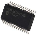
8Bit Microcontroller, Flash, PIC18F2xxx, 40MHz, 32KB, 1.5KB, 28Pins, SOIC
Updated Time: 2023/01/13 01:38:31 (UTC + 8)

PIC18F2520 Programming Manual Microcontrollers

56 Pages
Microchip
MICROCHIP PIC18F2520-I/ML 8Bit Microcontroller, Flash, PIC18F2xxx, 40MHz, 32KB, 1.5KB, 28Pins, QFN
56 Pages
Microchip
MCU 8Bit PIC RISC 32KB EPROM 5V 28Pin SPDIP Tube
56 Pages
Microchip
PIC PIC 18F Microcontroller IC 8Bit 40MHz 32KB (16K x 16) FLASH 28-QFN (6x6)
56 Pages
Microchip
MCU 8Bit PIC RISC 32KB EPROM 5V 28Pin SOIC W T/R

PIC18F2520-I/SO Specifications

TYPE
DESCRIPTION
Mounting Style
Surface Mount
Frequency
40 MHz
Number of Pins
28 Pin
Supply Voltage (DC)
5.00 V, 5.50 V (max)
Operating Voltage
4.2V ~ 5.5V
show more

PIC18F2520-I/SO Function Overview

The PIC18F2520-I/SO is an Enhanced Flash Microcontroller with 10-bit A/D and nanoWatt technology. The PIC18F2520 family introduces design enhancements that make these microcontrollers a logical choice for many high-performance and power sensitive applications. The PIC18F2520 family incorporates a range of features that can significantly reduce power consumption during operation. The PIC18F2520 device include an internal oscillator block which generates two different clock signals, either can be used as the microcontroller"s clock source. This may eliminate the need for external oscillator circuits on the OSC1 or OSC2 pins. The PIC18F2520 microcontroller can be serially programmed while in the end application circuit. This is simply done with two lines for clock and data and three other lines for power, ground and the programming voltage.
CPU - Up to 10 MIPS performance and C compiler optimized RISC architecture
System - Watchdog timer with separate RC oscillator
nanoWatt power managed modes - Run, idle and sleep modes
Analogue - 10 channels, 100kSPS and programmable brown-out reset module
Peripherals - Master synchronous Serial Port supports SPI ™ and I²C™ master and slave mode
100 years Typical flash/data EEPROM retention
Self-programmable under software control
Priority levels for interrupts
8 x 8 Single-cycle hardware multiplier
In-Circuit Debug (ICD) via two pins
ESD sensitive device, take proper precaution while handling the device.
show more
Part Datasheet PDF Search
Loading...
72,405,303 Parts Datasheet PDF, Update more than 5,000 PDF files ervery day.

Relate Parts