Web Analytics
Part Datasheet Search > Latches > CD4042 Datasheet PDF
Images are for reference

CD4042 Datasheet PDF

Part Series:
CD4042 Series
Category:
Latches
Description:
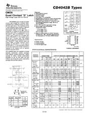
Latch Transparent 4Channel D-Type 16Pin Plastic Dip Tube
Updated Time: 2023/01/13 01:58:43 (UTC + 8)

CD4042 Datasheet PDF Latches

30 Pages
TI
Latch Transparent 4CH D-Type 16Pin SOP T/R
30 Pages
TI
Latch Transparent 4CH D-Type 16Pin SOIC Tube
30 Pages
TI
Latch Transparent 4CH D-Type 16Pin SOIC T/R
30 Pages
TI
Latch Transparent 4CH D-Type 16Pin CDIP Tube
30 Pages
TI
Latch Transparent 4CH D-Type 16Pin TSSOP Tube
30 Pages
TI
TEXAS INSTRUMENTS CD4042BEE4 Latch, CD4042, D Type, Differential, 40ns, 6.8mA, DIP
30 Pages
TI
Latch Transparent 4CH D-Type 16Pin CDIP Tube
30 Pages
TI
Latch Transparent 4CH D-Type 16Pin SOIC T/R
30 Pages
TI
Latch Transparent 4CH D-Type 16Pin SOIC Tube
30 Pages
TI
Latch Transparent 4CH D-Type 16Pin SOIC Tube
29 Pages
TI
Latch Transparent 4CH D-Type 16Pin TSSOP T/R
29 Pages
TI
IC QUAD CLOCKED D LATCH 16-SOIC
29 Pages
TI
IC QUAD CLOCKED D LATCH 16-SOIC
29 Pages
TI
IC QUAD CLOCKED D LATCH 16-SOIC
29 Pages
TI
IC QUAD CLOCKED D LATCH 16-TSSOP
29 Pages
TI
IC QUAD CLOCKED D LATCH 16-TSSOP

CD4042BE Specifications

TYPE
DESCRIPTION
Mounting Style
Through Hole
Number of Pins
16 Pin
Supply Voltage (DC)
15.0 V, 18.0 V (max)
Case/Package
PDIP-16
Number of Outputs
4 Output
show more

CD4042BE Function Overview

The CD4042BE is a CMOS Quad-clocked "D" Latch, each strobed by a common clock. Complementary buffered outputs are available from each circuit. The impedance of the n and p-channel output devices is balanced and all outputs are electrically identical. Information present at the data input is transferred to outputs Q and Q\ during the CLOCK level which is programmed by the POLARITY input. For POLARITY=0 the transfer occurs during the 0 CLOCK level and for POLARITY=1 the transfer occurs during the 1 CLOCK level. The outputs follow the data input providing the CLOCK and POLARITY levels defined above are present. When a CLOCK transition occurs (positive for POLARITY=0 and negative for POLARITY=1) the information present at the input during the CLOCK transition is retained at the output until an opposite CLOCK transition occurs.
Clock polarity control
Q and Q\ outputs
Common clock
Low power TTL compatible
Standardized, symmetrical output characteristics
100% Tested for quiescent current at 20V
show more
Part Datasheet PDF Search
Loading...
72,405,303 Parts Datasheet PDF, Update more than 5,000 PDF files ervery day.

Relate Parts