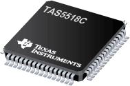
Part Datasheet Search > TI > TAS5518C Datasheet PDF

 Part 3D Model
$ 0
TAS5518C Datasheet PDF - TI
Manufacturer:
TI
Description:
8Channel Digital Audio PWM Processor 64-TQFP 0 to 70
Pictures:
3D Model
Symbol
Footprint
Pinout
Product Pictures
Documentation:
TAS5518C Datasheet PDF
AiEMA has not yet included the datasheet for TAS5518C
If necessary, please send a supplementary document request to the administrator

TAS5518C Datasheet PDF (104 Pages)
TAS5518C Function Overview
●The TAS5518C is an 8-channel digital pulse-width modulator (PWM) that provides both advanced performance and a high level of system integration. The TAS5518C is designed to interface seamlessly with most audio digital signal processors. The TAS5518C automatically adjusts control configurations in response to clock and data rate changes and idle conditions. This enables the TAS5518C to provide an easy-to-use control interface with relaxed timing requirements.
●The TAS5518C can drive eight channels of H-bridge power stages. Texas Instruments power stage parts TAS5111, TAS5112, or TAS5182 with FETs are designed to work seamlessly with the TAS5518C. The TAS5518C supports either the single-ended or bridge-tied-load configuration. The TAS5518C also provides a high-performance, differential output to drive an external, differential-input, analog headphone amplifier (such as the TPA112).
●The TAS5518C uses AD modulation operating at a 384-kHz switching rate for 48-, 96-, and
●192-kHz data. The 8× oversampling combined with the fifth-order noise shaper provides a broad, flat noise floor and excellent dynamic range from 20 Hz to 20 kHz.
●The TAS5518C is a clocked slave-only device. The TAS5518C receives MCLK, SCLK, and LRCLK from other system components. The TAS5518C accepts master clock rates of 128, 192, 256, 384, 512, and 768 fS. The TAS5518C accepts a 64-fS bit clock.
●The TAS5518C allows for extending the dynamic range by providing a power-supply, volume-control (PSVC) output signal.
● General Features
● Automated Operation With an Easy-to-Use
●Control Interface
● I2C Serial-Control Slave Interface
● Integrated AM Interference-Avoidance Circuitry
● Single, 3.3-V Power Supply
● 64-Pin TQFP Package
● 5-V Tolerant Inputs
● Audio Input/Output
● Automatic Master-Clock-Rate and
●Data-Sample-Rate Detection
● Eight Serial Audio Input Channels
● Eight PWM Audio Output Channels Configurable as
●Six Channels With Stereo Lineout or Eight Channels
● Line Output Is a PWM Output to Drive an External
●Differential-Input Operational Amplifier
● Headphone PWM Output to Drive an External Differential
●Amplifier Like the TPA112
● PWM Outputs Support Single-Ended and Bridge-Tied Loads
● 32-, 38-, 44.1-, 48-, 88.2-, 96-, 176.4-, and
●192-kHz Sampling Rates
● Data Formats: 16-, 20-, or 24-Bit Left-Justified, I2S,
●or Right-Justified Input Data
● 64-fS Bit-clock rate
● 128-, 192-, 256-, 384-, 512-, and 768-fS
●Master Clock Rates (Up to a Maximum of 50 MHz)
● Audio Processing
● 48-Bit Processing Architecture With 76 Bits of
●Precision for Most Audio-Processing Features
● Volume Control Range 36 dB to 127 dB
● Master Volume Control Range of 18 dB
●to 100 dB
● Eight Individual Channel Volume Control
●Ranges of 18 dB to 127 dB
● Programmable Soft Volume and Mute Update Rates
● Four Bass and Treble Tone Controls With ≥18-dB Range,
●Selectable Corner Frequencies, and Second-Order Slopes
● L, R, and C
● LS, RS
● LR, RR
● Sub
● Configurable Loudness Compensation
● Two Dynamic Range Compressors With Two Thresholds,
●Two Offsets, and Three Slopes
● Seven Biquads Per Channel
● Full 8×8 Input Crossbar Mixer. Each Signal-Processing
●Channel Input Can be Any Ratio of the Eight Input channels.
● 8×2 Output Mixer, Channels 16. Each Output is a Mix
●of Any Two Signal-Processed Channels. It is Recommended to
●Use the Pass-Through Output Mixer Configuration.
● 8×3 Output Mixer, Channels 7 and 8. Each Output Is a Mix of
●Any Three Signal-Processed Channels. It Is Recommended to Use
●the Pass-Through Output Mixer Configuration.
● Three Coefficient Sets Stored on the Device Can Be Selected
●Manually or Automatically (Based on Specific Data Rates).
● DC Blocking Filters
● Able to Support a Variety of Bass Management Algorithms
● PWM Processing
● 32-Bit Processing PWM Architecture With 40 Bits of Precision
● 8× Oversampling With Fifth-Order Noise Shaping at
●32 kHz-48 kHz, 4× Oversampling at 88.2 kHz and 96 kHz,
●and 2× Oversampling at 176.4 kHz and 192 kHz
● >110-dB Dynamic Range
● THD+N < 0.1%
● 20-Hz20-kHz, Flat Noise Floor for 44.1-, 48-, 88.2-, 96-,
●176.4-, and 192-kHz Data Rates
● Digital De-Emphasis for 32-, 44.1-, and 48-kHz Data Rates
● Flexible Automute Logic With Programmable Threshold and Duration
●for Noise-Free Operation
● Intelligent AM Interference-Avoidance System Provides
●Clear AM Reception
● Power-Supply Volume Control (PSVC) Support for Enhanced
●Dynamic Range in High-Performance Applications
● Adjustable Modulation Limit
●Matlab is a trademark of Math Works, Inc.
show more
TAS5518C Documents
TAS5518 Documents
TI
TEXAS INSTRUMENTS TAS5518PAG Audio Control, Digital Audio Interface, 3V to 3.6V, I2C, Serial, TQFP, 64Pins, 0 °C
Part Datasheet PDF Search
Example: STM32F103
Loading...
72,405,303 Parts Datasheet PDF, Update more than 5,000 PDF files ervery day.
BOM Matching ToolUpload BOM File
Matching parts
Alternative parts
Warning risks
Computing costs
File format: *.xlsx, *.xls, *.csv
Online 3D Gerber ViewerUpload Gerber File
Modeling in 15s
Preview PCB
40 types of layers
Preflight Risk
Support standard RS-274X file, accept zip rar or 7z
