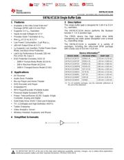
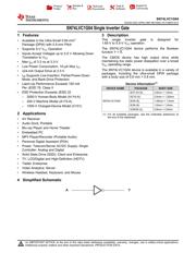
Web Analytics
Part Datasheet Search > Logic Gates > SN74LVC1G97 Datasheet PDF
Images are for reference

SN74LVC1G97 Datasheet PDF

Part Series:
SN74LVC1G97 Series
Category:
Logic Gates
Description:
Multi Function Gate 1Element 2IN CMOS 6Pin SC-70 T/R
Updated Time: 2023/01/13 02:30:09 (UTC + 8)

SN74LVC1G97 Datasheet PDF Logic Gates

38 Pages
TI
Multi Function Gate 1Element 2IN CMOS 6Pin SOT-23 T/R
33 Pages
TI
Multi Function Gate 1Element 2IN CMOS 6Pin SC-70 T/R
33 Pages
TI
Multi Function Gate 1Element 2IN CMOS 6Pin SOT-23 T/R
33 Pages
TI
Multi Function Gate 1Element 2IN CMOS 6Pin USON T/R
33 Pages
TI
Multi Function Gate 1Element 2IN CMOS 6Pin SC-70 T/R
33 Pages
TI
Multi Function Gate 1Element 2IN CMOS 6Pin SOT-23 T/R
33 Pages
TI
Multi Function Gate 1Element 2IN CMOS 6Pin SOT-563 T/R
33 Pages
TI
Multi Function Gate 1Element 2IN CMOS 6Pin DSBGA T/R
33 Pages
TI
Multi Function Gate 1Element 2IN CMOS 6Pin USON T/R
33 Pages
TI
Multi Function Gate 1Element 2IN CMOS 6Pin SC-70 T/R
33 Pages
TI
IC CONFIG MULT-FUNC GATE 6-DSBGA
33 Pages
TI
Multi Function Gate 1Element 2IN CMOS 6Pin SC-70 T/R
24 Pages
TI
Configurable Multiple-Function Gate
23 Pages
TI
Multi Function Gate 1Element 2IN CMOS 6Pin SC-70 T/R
16 Pages
TI
Multi Function Gate 1Element 2IN CMOS 6Pin SOT-23 T/R
15 Pages
TI
Multi Function Gate 1Element 2IN CMOS 6Pin SC-70 T/R

SN74LVC1G97DCKR Specifications

TYPE
DESCRIPTION
Mounting Style
Surface Mount
Number of Pins
6 Pin
Supply Voltage (DC)
1.65V ~ 5.50V
Case/Package
SC-70-6
Number of Outputs
1 Output
show more

SN74LVC1G97DCKR Function Overview

The SN74LVC1G97DCKR is a configurable Multiple-Function Gate. The output state is determined by eight patterns of 3-bit input. The user can choose the logic functions MUX and or, NAND, NOR, inverter and non-inverter. All inputs can be connected to VCC or GND. This configurable multiple-function gate is designed for 1.65 to 5.5V VCC operation. This device functions as an independent gate, but because of Schmitt action, it may have different input threshold levels for positive-going (VT+) and negative-going (VT-) signals. This device is fully specified for partial-power-down applications using Ioff. The Ioff circuitry disables the outputs, preventing damaging current backflow through the device when it is powered down.
±24mA Output drive at 3.3V
10µA Maximum ICC low power consumption
Inputs accept voltages to 5.5V
Maximum tpd of 6.3ns at 3.3V
Ioff supports live insertion, partial power down mode and back drive protection
Supports down translation to VCC
ESD protection exceeds JESD 22
Latch-up performance exceeds 100mA per JESD 78, Class II
Green product and no Sb/Br
show more
Part Datasheet PDF Search
Loading...
72,405,303 Parts Datasheet PDF, Update more than 5,000 PDF files ervery day.

Relate Parts