Part Datasheet Search > TI > SN74S163 Datasheet PDF

 Part 3D Model
$ 0
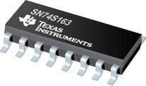
SN74S163 Datasheet PDF - TI
Manufacturer:
TI
Description:
4Bit Binary Counters
Pictures:
3D Model
Symbol
Footprint
Pinout
Product Pictures
Documentation:
SN74S163 Datasheet PDF
AiEMA has not yet included the datasheet for SN74S163
If necessary, please send a supplementary document request to the administrator

SN74S163 Datasheet PDF (23 Pages)
SN74S163 Environmental
SN74S163 Function Overview
●These synchronous, presettable counters feature an internal carry look-ahead for application in high-speed counting designs. The "160, "162, "LS160A, "LS162A, and "S162 are decade counters and the "161, "163, "LS161A, "LS163A, and "S163 are 4-bit binary counters. Synchronous operation is provided by having all flip-flops clocked simultaneously so that the outputs change coincident with each other when so instructed by the count-enable inputs and internal gating. This mode of operation eliminates the output counting spikes that are normally associated with asynchronous (ripple clock) counters, however counting spikes may occur on the (RCO) ripple carry output. A buffered clock input triggers the four flip-flops on the rising edge of the clock input waveform.
●These counters are fully programmable; that is, the outputs may be preset to either level. As presetting is synchronous, setting up a low level at the load input disables the counter and causes the outputs to agree with the setup data after the next clock pulse regardless of the levels of the enable inputs. Low-to-high transitions at the load input of the "160 thru "163 should be avoided when the clock is low if the enable inputs are high at or before the transition. This restriction is not applicable to the "LS160A thru "LS163A or "S162 or "S163. The clear function for the "160, "161, "LS160A, and "LS161A is asynchronous and a low level at the clear input sets all four of the flip-flop outputs low regardless of the levels of clock, load, or enable inputs. The clear function for the "162, "163, "LS162A, "LS163A, "S162, and "S163 is synchronous and a low level at the clear input sets all four of the flip-flop outputs low after the next clock pulse, regardless of the levels of the enable inputs. This synchronous clear allows the count length to be modified easily as decoding the maximum count desired can be accomplished with one external NAND gate. The gate output is connected to the clear input to synchronously clear the counter to 0000 (LLLL). Low-to-high transitions at the clear input of the "162 and "163 should be avoided when the clock is low if the enable and load inputs are high at or before the transition.
●The carry look-ahead circuitry provides for cascading counters for n-bit synchronous applications without additional gating. Instrumental in accomplishing this function are two count-enable inputs and a ripple carry output. Both count-enable inputs (P and T) must be high to count, and input T is fed forward to enable the ripple carry output. The ripple carry output thus enabled will produce a high-level output pulse with a duration approximately equal to the high-level portion of the QA output. This high-level overflow ripple carry pulse can be used to enable successive cascaded stages. High-to-low level transitions at the enable P or T inputs of the "160 thru "163 should occur only when the clock input is high. Transitions at the enable P or T inputs of the "LS160A thru "LS163A or "S162 and "S163 are allowed regardless of the level of the clock input.
●"LS160A thru "LS163A, "S162 and "S163 feature a fully independent clock circuit. Changes at control inputs (enable P or T, or load) that will modify the operating mode have no effect until clocking occurs. The function of the counter (whether enabled, disabled, loading, or counting) will be dictated solely by the conditions meeting the stable setup and hold times.
●## "160, "161, "LS160A, "LS161A … SYNCHRONOUS COUNTERS WITH DIRECT CLEAR "162, "163, "LS162A, "LS163A, "S162, "S163 … FULLY SYNCHRONOUS COUNTERS
● Internal Look-Ahead for Fast Counting
● Carry Output for n-Bit Cascading
● Synchronous Counting
● Synchronously Programmable
● Load Control Line
● Diode-Clamped Inputs
show more
SN74S163 Documents
SN74 Documents
TI
Shift Register, HC Family, 74HC164, Serial to Parallel, 1Element, 8Bit, DIP, 14Pins
TI
Inverter, Schmitt Trigger, 74LVC1G14, 1Input, 32mA, 1.65V to 5.5V, SOT-23-5
TI
Inverter Schmitt Trigger 6Element CMOS 14Pin TSSOP Inverter Schmitt Trigger 6Element CMOS 14Pin TSSOP
TI
Inverter, Schmitt Trigger, 74AHC1G14, 1Input, 8mA, 2V to 5.5V, SOT-23-5
TI
TEXAS INSTRUMENTS SN74LVC4245APWR Transceiver, Non-Inverting, 2.7V to 3.6V, 4.5V to 5.5V, TSSOP-24
TI
Flip-Flop, Differential / Complementary, Positive Edge, 74LVC74, D, 4.1ns, 200MHz, 32mA, VSSOP
Part Datasheet PDF Search
Example: STM32F103
Loading...
72,405,303 Parts Datasheet PDF, Update more than 5,000 PDF files ervery day.
BOM Matching ToolUpload BOM File
Matching parts
Alternative parts
Warning risks
Computing costs
File format: *.xlsx, *.xls, *.csv
Online 3D Gerber ViewerUpload Gerber File
Modeling in 15s
Preview PCB
40 types of layers
Preflight Risk
Support standard RS-274X file, accept zip rar or 7z
